Introduction
No home is complete without a full cabinet of food! Read below for how I managed to make this happen. This part of the build is also where I will have electrical wires, switches and my battery monitor installed.
materials used
- 12 Feet of 1" X 4" Oak ($21.99 at Home Depot)
- Extra 8' pine panel boards (Purchased Earlier)
- Two (2) 2" X 3" by 8' studs ($2.59 each at Home Depot)
- Rivet Nuts and 1/4" by 20 count bolts (Purchased Earlier)
- Two (2) Liberty Brand Inlay Cabinet Hinges ($6.59/Pair at Home Depot)
- Extra 1/4" MDF board (Purchased Earlier)
- Prefinished 8' X 1' X 1/2" thick furniture siding panel ($40 at Ikea)
- More 2.5" Kreg screws ($6.99 at Home Depot)
- 2.5" long 1/4" X 20 thread count hex bolts (Purchased Earlier)
Total Material Cost: $80.75 US Dollars
tools used
- Table Saw with Cutting and Dato Blades
- Router with Various Bits
- Palm Sander
- Drills and Bits/Drives
- Kreg Hole Jig
- C-Clamps
- Pipe clamps
- Carpenters Square and Measuring Tape
- Socket Set
- Vice Grips and Box Wrenches (For Installing Rivet Nuts)
- Router with Various Bits
- Palm Sander
- Drills and Bits/Drives
- Kreg Hole Jig
- C-Clamps
- Pipe clamps
- Carpenters Square and Measuring Tape
- Socket Set
- Vice Grips and Box Wrenches (For Installing Rivet Nuts)
Time Spent on Job: 8 Hours (does not include time to route electrical wiring and install electrical components)
step 1 - build frame and side panels
**Note that I needed to have the electrical system compartment completed before I could build this cabinet as that sits directly below. See the details about that in the electrical system article.
I started by again, building a frame out of some extra 2" X 3" studs I had. There was a few longer pieces I had to include to bring the frame from the top of the electrical cabinet below, to the ceiling of the van, therefore I did have to buy a couple 8' pieces as well. I simply cut each piece to a measured length, and assembled as I went, securing the top to the van wall with the rivet nuts and bolts. In order to line up onto a couple of the existing holes in the van panel, and to add strength, I also used a couple 90 degree angle braces my dad had laying around. Tilting the blade of the table saw and cutting out pieces at whatever angles the van required was how I fit them all in. Since the hinges I have for the doors are all 1.25" offset inlay hinges, to get the edge of the door to be flush with the outer edge of the 1/2" thick prefinished side panel, I had to notch out a 3/4" section of the 1.5" thick stud (thus leaving 3/4" left plus the 1/2" side panel for the door to sit flush). I then used cardboard to cut out a template for each of the two side panels and cut them out using the jig saw. It took a few dry fits to get it just right. I then screwed them to the frameboards whereever the side panel would be hidden from something else. Where I knew it would be visible, I used angle brackets from the inside.
I started by again, building a frame out of some extra 2" X 3" studs I had. There was a few longer pieces I had to include to bring the frame from the top of the electrical cabinet below, to the ceiling of the van, therefore I did have to buy a couple 8' pieces as well. I simply cut each piece to a measured length, and assembled as I went, securing the top to the van wall with the rivet nuts and bolts. In order to line up onto a couple of the existing holes in the van panel, and to add strength, I also used a couple 90 degree angle braces my dad had laying around. Tilting the blade of the table saw and cutting out pieces at whatever angles the van required was how I fit them all in. Since the hinges I have for the doors are all 1.25" offset inlay hinges, to get the edge of the door to be flush with the outer edge of the 1/2" thick prefinished side panel, I had to notch out a 3/4" section of the 1.5" thick stud (thus leaving 3/4" left plus the 1/2" side panel for the door to sit flush). I then used cardboard to cut out a template for each of the two side panels and cut them out using the jig saw. It took a few dry fits to get it just right. I then screwed them to the frameboards whereever the side panel would be hidden from something else. Where I knew it would be visible, I used angle brackets from the inside.
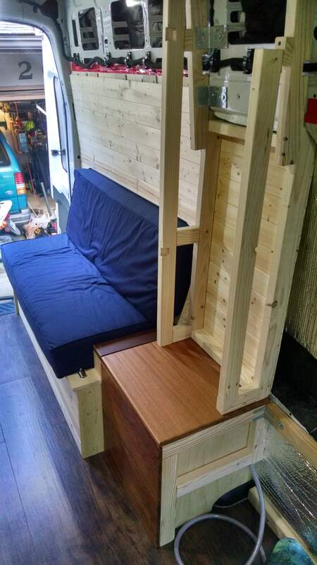
Building the framework. Notice the notches in the left side where the door hinges will go
|
Side panels cut to fit and screwed onto the frame.
|
step 2 - build door
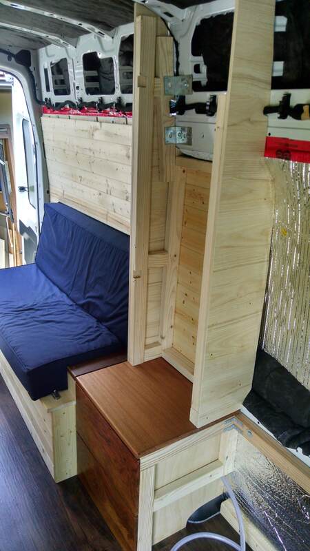
Just like all the other cabinet doors I made, I took a 12' long 1" X 4" oak board and using the dato blade on the table saw, cut a 5/16" dato to a depth of 3/8" along the entire edge of one side of the board for the pine panels to slip into. I then cut it to length for each of the 4 pieces, carefully measuring out exactly how tall and wide it needed to be also accounting for the 3/8" toungue on both ends of the two horizontal pieces (which will also slip into the dato on the vertical pieces). I then cut about 10 pieces of the pine paneling long enough to fit into the dato groove and then assembled the door. I only glued the oak pieces together, leaving the pine panels floating inside. Once the glue dried, I stained the entire door with gel stain (I recommend Emmet's Good Stuff brand, the finish is vibrant and remarkable), then I used the router to cut out two 1-3/8" diameter circles deep enough for the inlay hinge to fit into. I had to ensure I measured exactly where to cut out these two circles so they matched up with my notches I previously made in the left side frame piece. With the hinges onto the door, I could install the door and add the latch to hold it closed. Note that the bottom segment of the door is separate (as shown in the photo below) and doesn't open. This was to allow me to still be able to open the door when the folding bed is down (since it rests on the red tabletop, and the couch shown at the bottom of the photo).
The pantry exterior completed
step 3 - Build the interior shelving
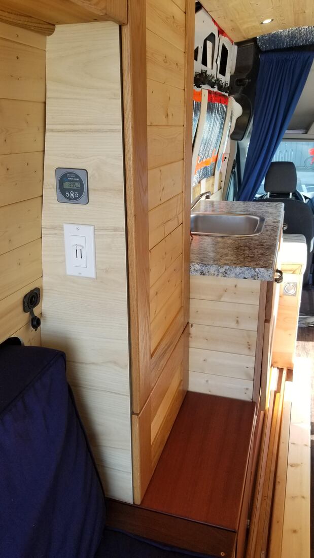
The inside of this particular cabinet actually has many purposes. Obviously there are some shelving inside for various food items, but there is also a spot where wiring from the rooftop solar panels are run down one of the frameboards. Since the electrical compartment and battery is located in the space immediately below, it was an obvious path to run any wiring that needed to go from the floor area to the ceiling. More info about this can be found in the electrical system page. I also installed my battery monitor and dual zone dimmer switch for the LED lights on this side panel, with the wiring running along a conduit inside. These are shown in the photo above.